Wedging is the process of kneading clay to remove air bubbles before use. A wedging table is a low, study table with an absorbant surface (a concrete paving slab can be used) for wedging. A wedging table was required. I built one using softwood timber which had been found free on Freecycle.
Design

Five key inputs determined the design of the table: the desired height of the upper surface (77 cm); the dimensions of the paving slab (40 cm by 40 cm by 28 mm); the width of the wood used to frame the slab (33 mm); the tolerance between the slab’s and the frame’s sides (3 mm on each side); and the actual dimensions of the ‘2 by 4’ timber (39 mm by 65 mm). The surface height was found by assuming it should be distance between the tips of the fingers of the intended user and the floor, if she stood with her hands by her side. Once the table was built, I found that the 3 mm tolerance was more generous than necessary.
The table top would be 472 mm square (33 mm + 3 mm + 400 mm + 3 mm + 33 mm). The slab and its frame would sit on a sheet of 18 mm thick hardwood plywood.
The legs would be ‘4 by 4’, made by putting lengths of ‘2 by 4’ back to back. The main leg pieces would be 724 mm in length (770 mm – 28 mm – 18 mm). The two front legs, viewed from the front, would be joined at the top and 100 mm from the floor by horizontal ‘2 by 4’ pieces. The infill vertical pieces would be, consequently, 100 mm and 494 mm (724 mm – 100 mm – 65 mm – 65 mm) in length. The back legs would be the same as the front legs.
The front and back structures would be joined by four horizontal ‘2 by 4’ pieces, two at the top and two 100 mm from the floor, placed inside the legs. They would be 394 mm (472 mm – 39 mm – 39 mm) in length.
A rectangle of 18 mm thick hardwood plywood would be joined to the lower horizontal pieces, both strengthening the structure and acting as a sturdy lower shelf for materials such as unwedged clay. I allowed a tolerance of 2 mm, so its width would be 338 m (472 mm – 65 mm – 2 mm – 2mm – 65 mm) and length 472 mm.
The frame around the slab would be built from four pieces of planed redwood 27 mm by 33 mm, two of length 472 mm and two of length 406 mm (472 mm – 33 mm – 33 mm). This height (27 mm) meant that the surface of the paving slab (28 mm thick) would sit a little proud of the frame.
Materials
The total cash cost of the materials was about £ 64, but with a value of about £ 152.
A total length of ‘2 by 4’ of 8.736 m was required, before cuts and wastage. That would have cost at least about £ 88 at retail prices, but was obtained at no cost. The free timber had some existing screw holes but I was able to make use of some and hide most of the others, given the way that the wood would be used.
18 mm plywood is difficult to cut acurately. Cut My Plastic delivered two precisely cut pieces ( 472 mm square and 338 mm by 472 mm) for £ 28.48. Softwood plywood would have reduced the cost by about 30%.
A total length of 27 mm by 33 mm planed redwood of 1.756 m was required. A standard length of 1.8 m cost £ 9.40.
A single paving slab cost £ 2.79, from B & Q.
The ‘2 by 4’ was joined using 4 mm x 70 mm, SPAX YELLOX screws, 80 of them, at a cost of about £ 13.60. The plywood was secured using 3.5 mm x 50 mm SPAX YELLOX screws, 16 of them, at a cost of about £ 0.80. The slab frame was wood glued and clamped.
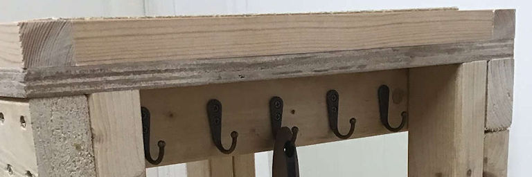
The addition of 10 small bronze-coloured metal hooks cost £ 8.99.
Construction
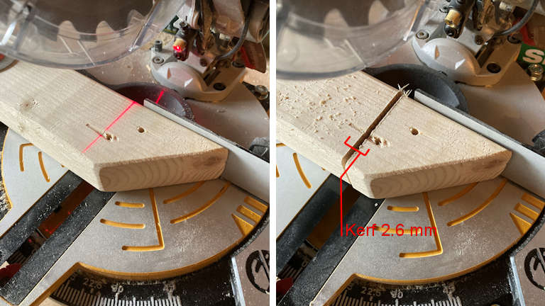
It would be important that pieces intended to be the same length were the same length and that cut faces were perpendicular to planed faces. I needed a powered mitre saw for the cross cuts, and purchased a simple one with a laser guide for £ 75.
The red laser guide was useful in positioning pieces of wood to be cut. From use, I learned that the blade would cut very slightly to the left of the laser’s line. Occasionally, depending on which length of wood I needed to preserve, I would need to take into account the blade’s kerf (the width of the cut, said to be 2.6 mm).
I used a handmade stop block to ensure that subsequent pieces were cut to the same length as the first pieces. I cut, in order, the four 724 mm main leg pieces, the four 100 mm lengths, and the two sets of four horizontal pieces from the ‘2 by 4’, and drilled guide holes for screws, including the holes for the hortizontal pieces that would attach the front and back. For the latter guide holes, I used a drill guide to help ensure the holes were perpendicular to the face. I attached the 100 mm lengths and the front and back cross pieces to the main leg pieces, each with four 70 mm screws, checking to make sure that faces intended to be flush were flush and that they were square.
I then re-measured, cut, and fitted, the 494 mm vertical infill ‘2 by 4’ pieces, which would be more for appearance than for structural reasons.
I then fitted the four horizontal pieces that attached the front and back with two 70 mm screws at each end, fitting them all simultaneously. The guide holes had already been drilled. This required careful checking to make sure that faces intended to be flush were flush and that everything remained square as screws were tightened. With the benefit of hindsight, more clamps would have made this step easier and more reliable.
If everything was true and square, the table frame would not wobble on its legs on a level surface and the two diagonals should be 667.5 mm. The measured diagonals were about 665 mm and 670 mm, so I was about 0.5 degree off perpendicular, which was tolerable.
I attached the lower plywood shelf with eight 50 mm screws and then the plywood top with another eight, taking care to avoid the locations of other screws. I drilled guide holes in the hardwood plywood and used a countersink drill to ensure that the screwheads would be countersunk. Countersinking had not been necessary for the screws into the softwood ‘2 by 4’.
I glued and screwed (from below, through the plywood) the side frames for the slab, using clamps until the glue had set. The screws were likely unnecessary as wood glue alone, across a large enough surface, is stronger than screws. I then placed the slab (after washing off some dust from scrapes and scratches) and glued the front and back frames for the slab.
The inset side pieces under the table’s top allowed for the addition of hooks. These would provide somewhere to hang tools, such as a cutting wire, used during wedging.
Result
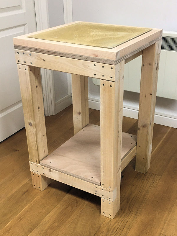
The result was as I had intended – a sturdy table which stood firm on a level floor.
Careful measurement and cutting meant that the faces were flush. Only a little light sanding was required to smooth surfaces.
If wood glue is as strong as screws, perhaps an all-glue construction method could have been used (if I had some more clamps and taken more time for the glue to set). However, the regular placement of the screwheads does not detract from the appearance and perhaps helps to convey the table’s strength.