Summary
A three-digit initial state, determined by three 4-position dual inline (DIL) switches, is set by pressing Switch 1 (SW1). Pressing Switch 2 (SW2) starts a count down to zero. When zero is reached, the light emitting diode (LED) lights up. The progress of the count is shown by a three-digit seven-segment liquid crystal display (LCD).
Circuit
Schematic
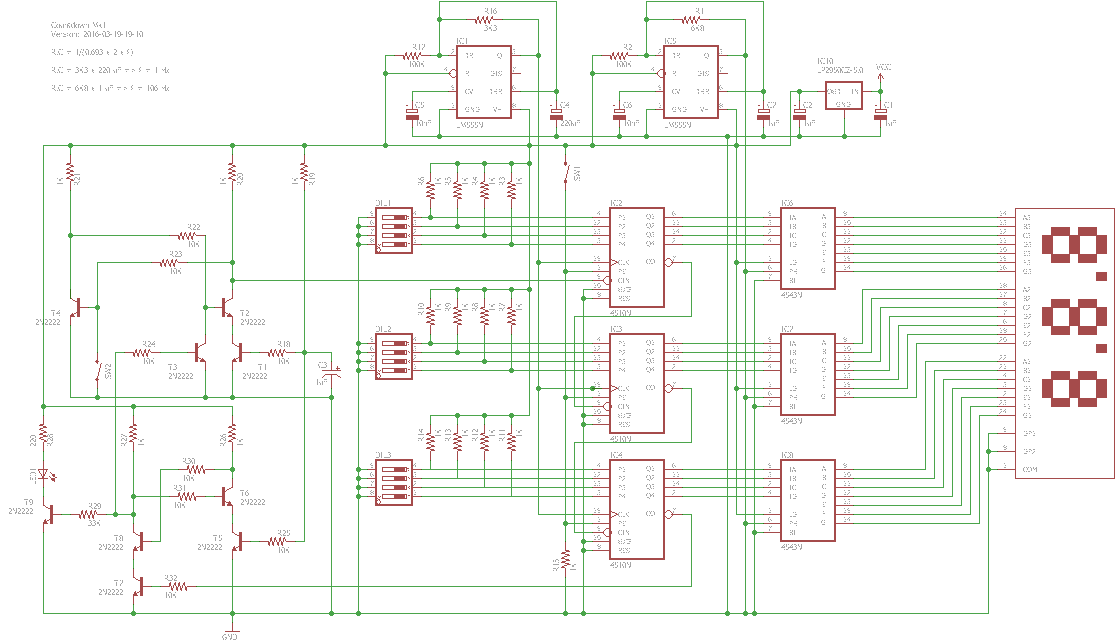
An LP2950 5.0 V micropower voltage regulator was used to ensure that the voltage supplied to the circuit was 5.0 V irrespective of the voltage of the power supply.
Resistor R19 and capacitor C3 act as a power-on reset, ensuring that transistors T1 and T5 are initially switched off and the collectors of transistors T2 and T6 (respectively) are high. Transistors T1 and T5 then turn on as capacitor C3 charges.
An LM555 integrated circuit (IC) was used as an astable multivibrator. The intent was a square wave with a 50% duty cycle, one at about 1 Hz for the count down and one at about 100 Hz to drive the LCD.
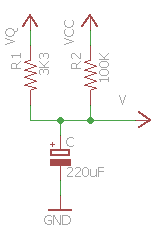
Various web sites suggested that the output (Q, pin 3) could be connected to ground through a resistor (R16 or R1) and a capacitor (C4 or C7) and the trigger (TR, pin 2) and the threshold (THR, pin 6) could be connected to the anode of the capacitor, to achieve a 50% duty cycle with frequency:
f = 1 / [2 x (ln 2) x RC]
ln 2 is about 0.693.
However, that approximation does not take into account that when output is high (VQ), it can be up to 2.25 V below the supply voltage (VCC) and is typically 1.7 V below.
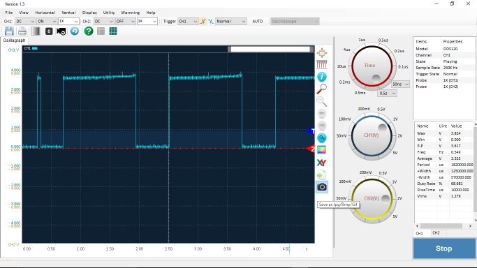
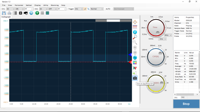
As built, the output voltage of the first timer was about 3.6 V and the period 1.82 seconds with a duty cycle of almost 70%.
As built, the output voltage of the second timer was about 4.0 V and the period 0.141 seconds (frequency of 71 Hz) with a duty cycle of over 60%. A duty cycle other than 50% is problematic for driving an LCD because it implies that there is a direct current (DC) component across the LCD segments. In time, that can damage the LCD.
The period for charging between V_low (VCC x 1/3) and V_high (VCC x 2/3) is:
t1 = ln [(V1 – V_low) / (V1 – V_high)] x RC
and the period of discharging from V_high to V_low is:
t2 = ln [(V_high – V2) / (V_low – V2)] x RC
where:
V1 = VQ x R/R1 + VCC x R/R2
V2 = VCC x R/R2
1/R = 1/R1 + 1/R2
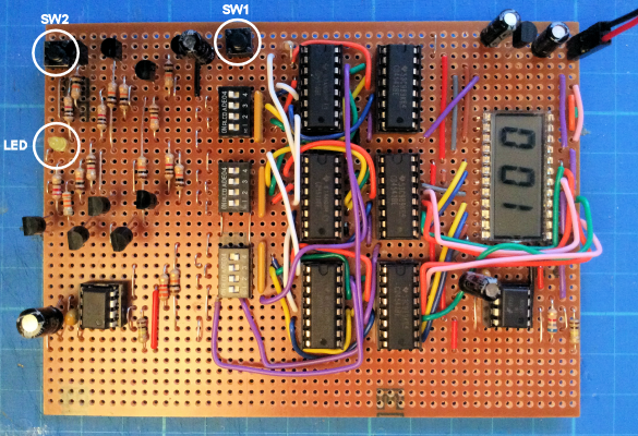
Stripboard
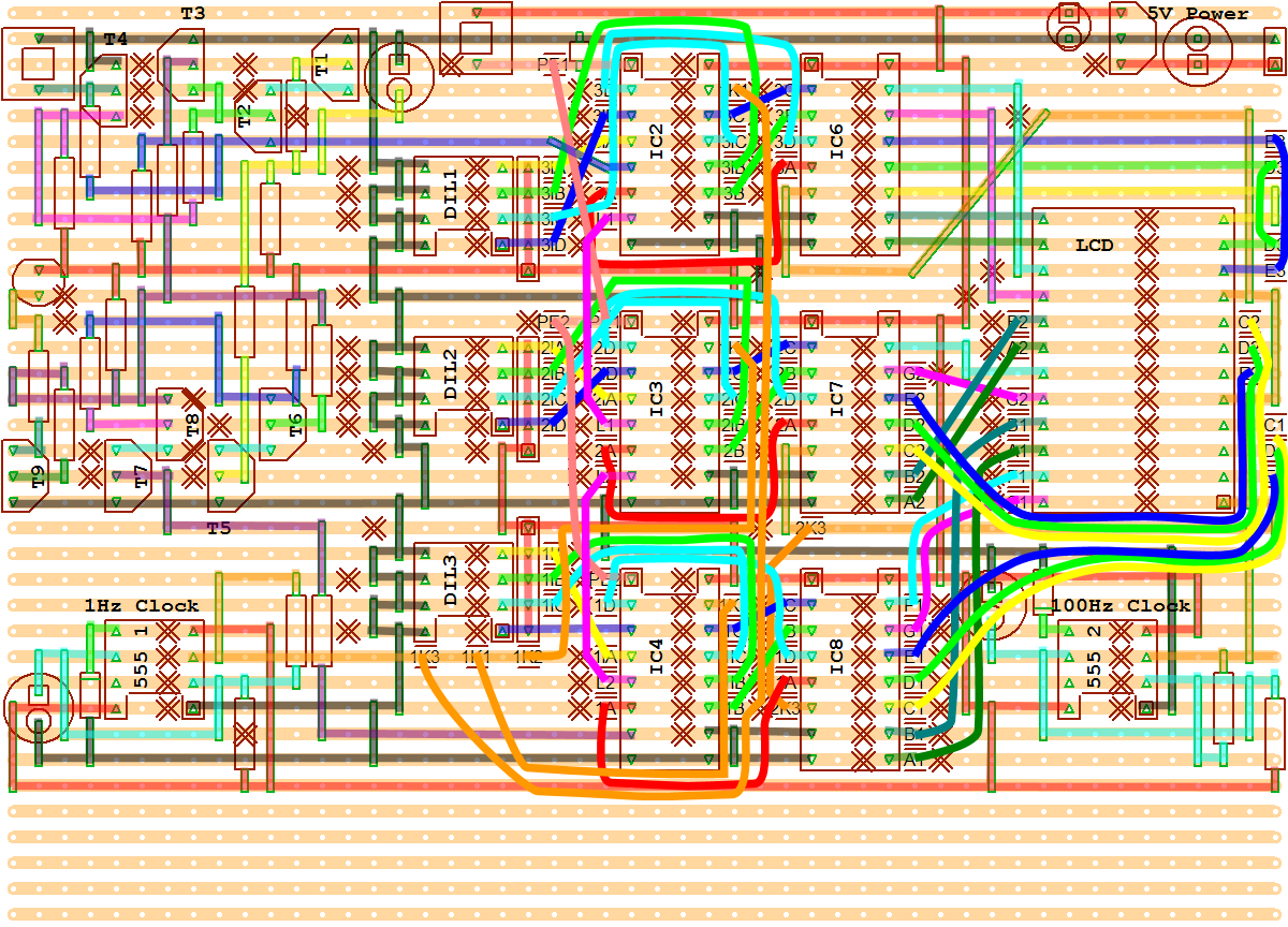
The stripboard size is 36 tracks of 50 holes.