Summary
The circuit adds two four-bit numbers. The input is by means of a single eight-position DIP (dual in-line package) switch. The output is displayed using a five-bar LED (light-emitting diode) bar graph.
Circuit
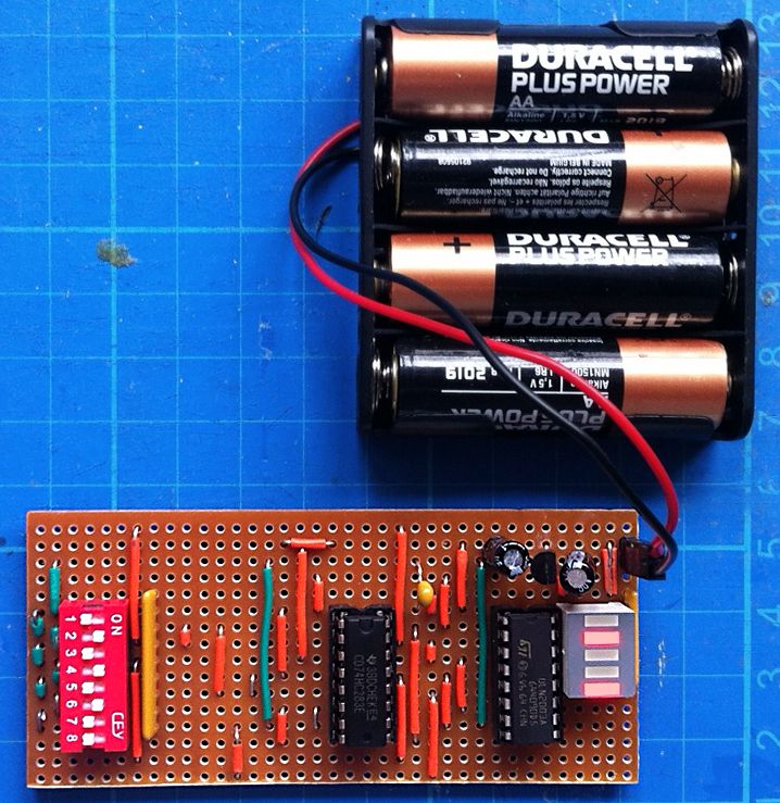
The least significant digits are highest in the image. Switches 4 to 1 are one input and switches 8 to 5 are the other. When a switch is off (to the left), the input to the adder is pulled high (switch off = 1). When a switch is on (to the right), the input is pulled low (switch on = 0).
The image shows 0101 (5) plus 1101 (13) equals 10010 (18).
The short horizontal wire was unplanned and added to fix damage done to a copper strip during soldering.
Schematic
The circuit was originally intended to be powered by four AA batteries, each with a nominal voltage of 1.5 V (6 V in total). The batteries are relatively fresh and have a measured voltage of 6.2 V.
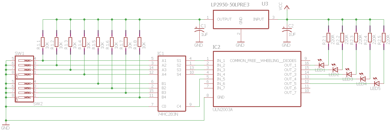
Each of the LEDs in the bar graph is rated as having a typical forward voltage of 2.0 V (with a maximum of 2.5 V).
To limit the current through each LED to about 20 mA, a resistor of about 210 Ω is required in series.
(6.2 V – 2.0 V) / 20 mA = 210 Ω
The closest preferred value in the E24 series is 220 Ω.
The adder itself is an IC (integrated circuit) manufactured by Texas Instruments: the CD74HC283E, a high-speed CMOS logic 4-bit binary full adder with fast carry.
The operating supply voltage range of the IC is 2 V to 6 V, with an absolute maximum of 7 V. The circuit regulates the supply voltage at 5 V.
The voltage is regulated using an LP2950 micropower voltage regulator (LP9250ACZ-5.0), with an output capacitor of 1 µF and an input capacitor of 1 µF.
It may not have been necessary, but a 10 nF decoupling capacitor is placed between the supply to the adder IC and ground.
The carry-in input is not used and is tied low.
Each other input is held high (when the DIP switch is open) through a 10 kΩ pull-up resistor.
The LEDs are driven through Darlington pairs. The ULN2003A IC provides seven open collector pairs with common emitters. Five pairs are used. The common free-wheeling diodes (pin 9) are not used.
Stripboard
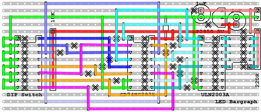
The stripboard is 16 tracks of 37 holes, made by scoring and snapping a larger piece of 24 by 37 board.