Autodesk’s Fusion 360 allows the parametric modelling of solids. I used it to create a better pill box, where user parameters defined the box diameter (default 38 mm), box height (3 times the radius, between the hemispherical caps), wall thickness (2 mm), minimum wall thickness (0.8 mm), clearance (between the overlapping parts) (0.25 mm), number of turns for the thread (5) and the dimensions of the thread profile (width and height of the internal thread of 1 mm).
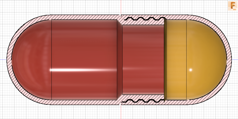
The two halves of the pill were modelled by joining cylinders and spheres. Overhangs were converted into 45° slopes using the Fillet tool. The Shell tool converted the solid into a hollow cavity. The Fillet tool was used again to ensure that 45° slopes would marry.
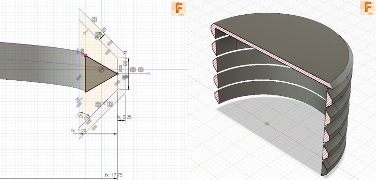
Fusion 360 does not have a tool to create a helix but does have a Coil tool to create a solid coil. This was used to extract two helices (one for a path and the other for a guide rail). The custom profile for the thread (external and internal) was sketched and based on a trapezoidal thread form with a 90° thread angle (to avoid the need for any supports on 3D printing). The Sweep tool converted the relevant profile, using the path and guide rail, into a solid which was joined to the internal cylindrical shell (for the external thread) or cut from the external cylindrical shell (for the internal thread). The Split Body tool was used to ensure the end of the solid in question was co-planar with the end face of the relevant cylindrical shell.
In the case of the cutting solid for the internal thread, a truncated right circular cone of 45° was joined to the top to eliminate any overhangs which would otherwise need support when 3D printing. The truncated cone was created by extruding a sketched circle with a negative 45° taper.