Summary
The circuit is a SR (set-reset) latch. The input is by means of a two tactile switches (set and reset). The output is displayed using two LEDs (red and yellow for Q and not Q).
Circuit
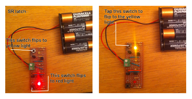
Originally, the power connector was a two-position screw terminal (as in the images above). This was replaced with two header pins.
Schematic
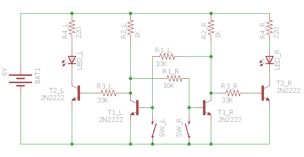
The circuit was originally intended to be powered by four AA batteries, each with a nominal voltage of 1.5 V (6 V in total). The batteries are relatively fresh and have a measured voltage of about 6.4 V.
Each of the LEDs is rated as having a forward voltage between 2.0 V and 2.4 V.
To limit the current through each LED to about 20 mA, a resistor of about 220 Ω is required in series.
(6.4 V – 2.0 V) / 20 mA = 220 Ω
220 Ω is a preferred value in the E24 series.
Each LED is driven through a 2N2222 NPN transistor. The following assumes that the base-emitter voltage of the transistor is 0.6 V.
If transistor T1_L is on and transistor T1_R is off, then the voltage at the collector of T1_R is about 5.3 V.
(6.4 V – 0.6V) x 10 kΩ / (10 kΩ + 1 kΩ) = 5.3 V
The base current of transistor T2_R is about 0.14 mA.
(5.3 V – 0.6V) / 33 kΩ = 0.14 mA
The current gain of transistor T2_R is sufficient for the current through its collector to allow LED_R to illuminate.
Stripboard
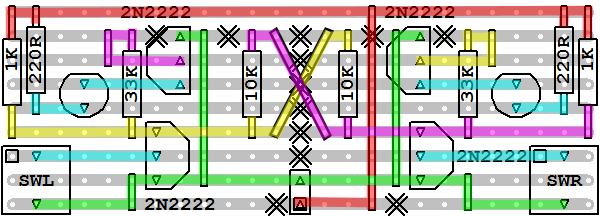
The stripboard size is 9 tracks of 25 holes.